QO-100 Transceiver
On the internet you can find many ways how amateurs have made there transceiver with transverters or an SDR Radio.
I found that it would be nice to have it all in one unit, that can be controlled over network like my other SDR transceiver from Apache Labs 200D.
For that, the ADALM Pluto is great, and a big plus is that it can transmit and receive at the same time – Full Duplex.
Following items are in my transceiver:
1. ADALM Pluto Analog Devices Rev. C/D
2. POTY Feed. Kit bought a from passion-radio.com
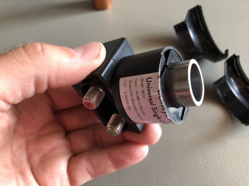
3. LNB – Othernet Bullseye – because it has a good frequency stablility
4. Bandpass filter for receive signal 739 Mhz
5. Bandpass filter for transmit signal 2,4 Ghz
6. Preamplifier CN-0417 Analog Devices
7. Bias Tee to insert power for LNB
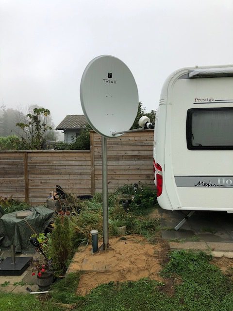
8. Offset satellite dish – Triax TDS100LG – 87 x 97 cm
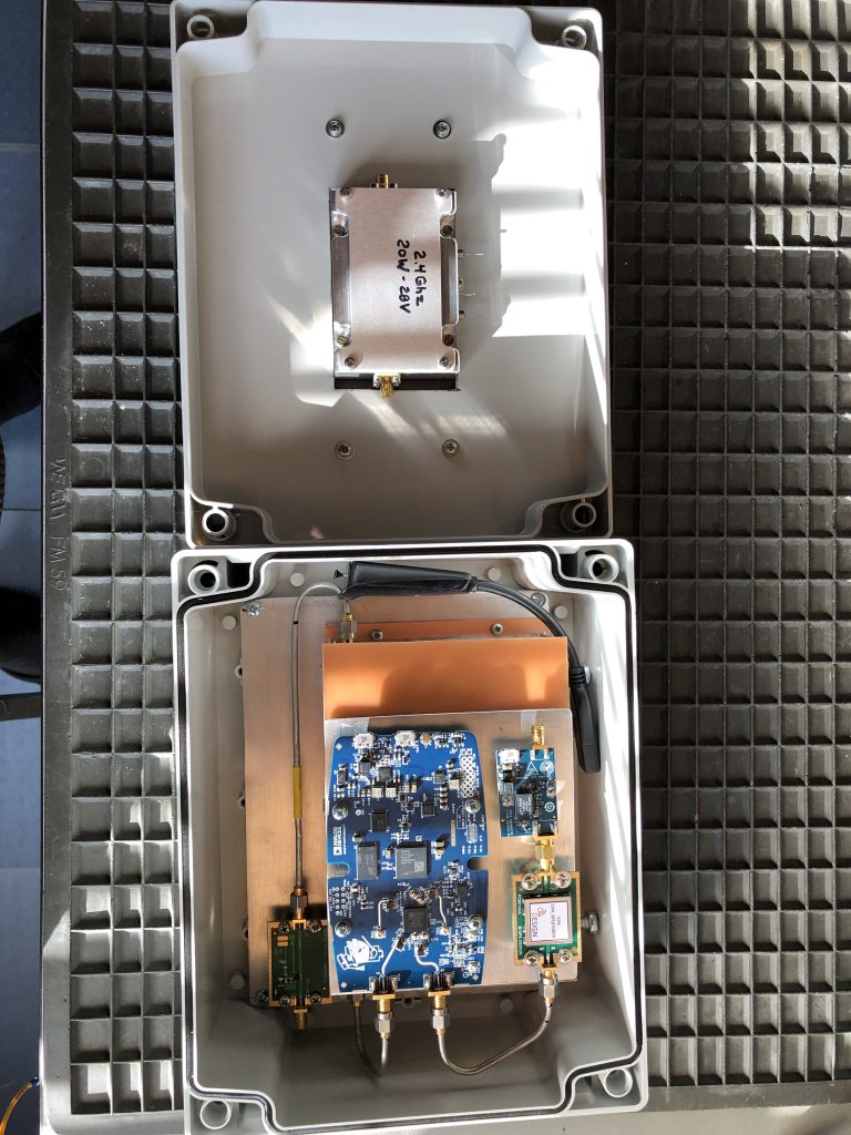
9. 2.4 Ghz PA. SG-LABS 20W. About 5 Watts are needed for good signal on QO-100
10. Power supply 12V and 24 Volt for the PA
11. Water tight Box for mounting it outside behind the dish
12. Leo Bodnar GPSDO Mini
ADALM Pluto
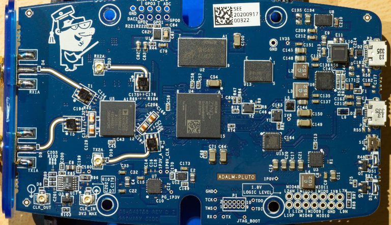
I bought the ADALM Pluto from Mouser.com, because of the new import rules in denmark, and also to get the newest revision D. It has the input for external clock that is a problem for the frequenz stability when transmitting. It needs a 40 Mhz clock with max. 3.3V from a GPSDO. Leo Bodnar Mini will be the best unit for fitting it in my box and operates also on 5V like the Pluto.
The Pluto was taken out of its shell and mounted on top of the receive filter – that is described later.
Pluto and the Preamplifier CN-0417 from Analog Devices, are both getting 5V from a mini 12V to 5V Power Supply, but the CN-0417 is getting very hot all the time. I therefore switch the 5V for CN-0417 on/off with a relay coupled to the PTT out from Pluto. The same PTT goes also to the SG-Labs PA module.
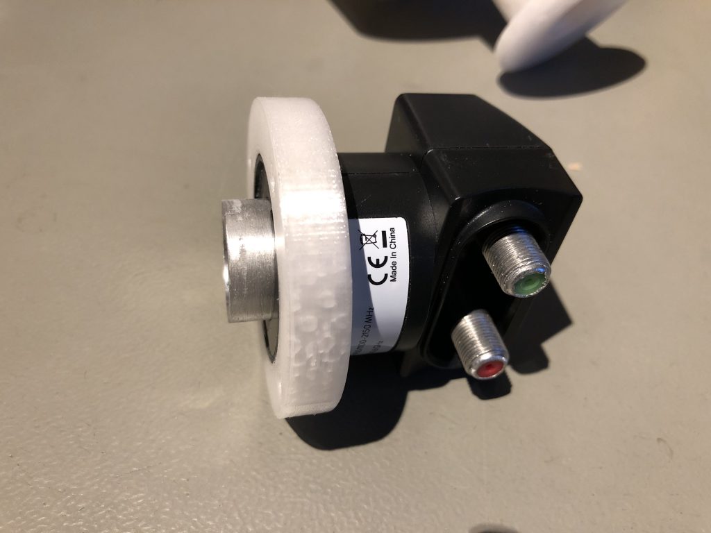
POTY Feed assembly and LNB
First of all, I assembled the POTY feed, that came as a kit from Passion-radio.com. On the internet I saw many are using this feed to receive and transmit on QO-100.
The feed is soldered together with very little solder and a hot airgun. It’s no problem to place the plates it in right distance, because the kit is made for it. Only thing is to place the feeds top plate the right way, to give it the right circular direction. When soldering the two plates, I placed two 3.0mm drills between the plates.
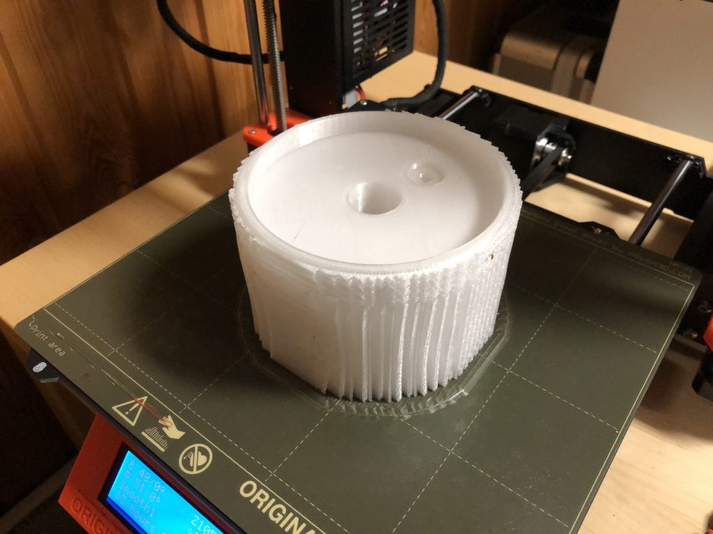
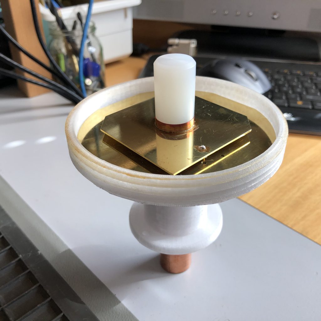
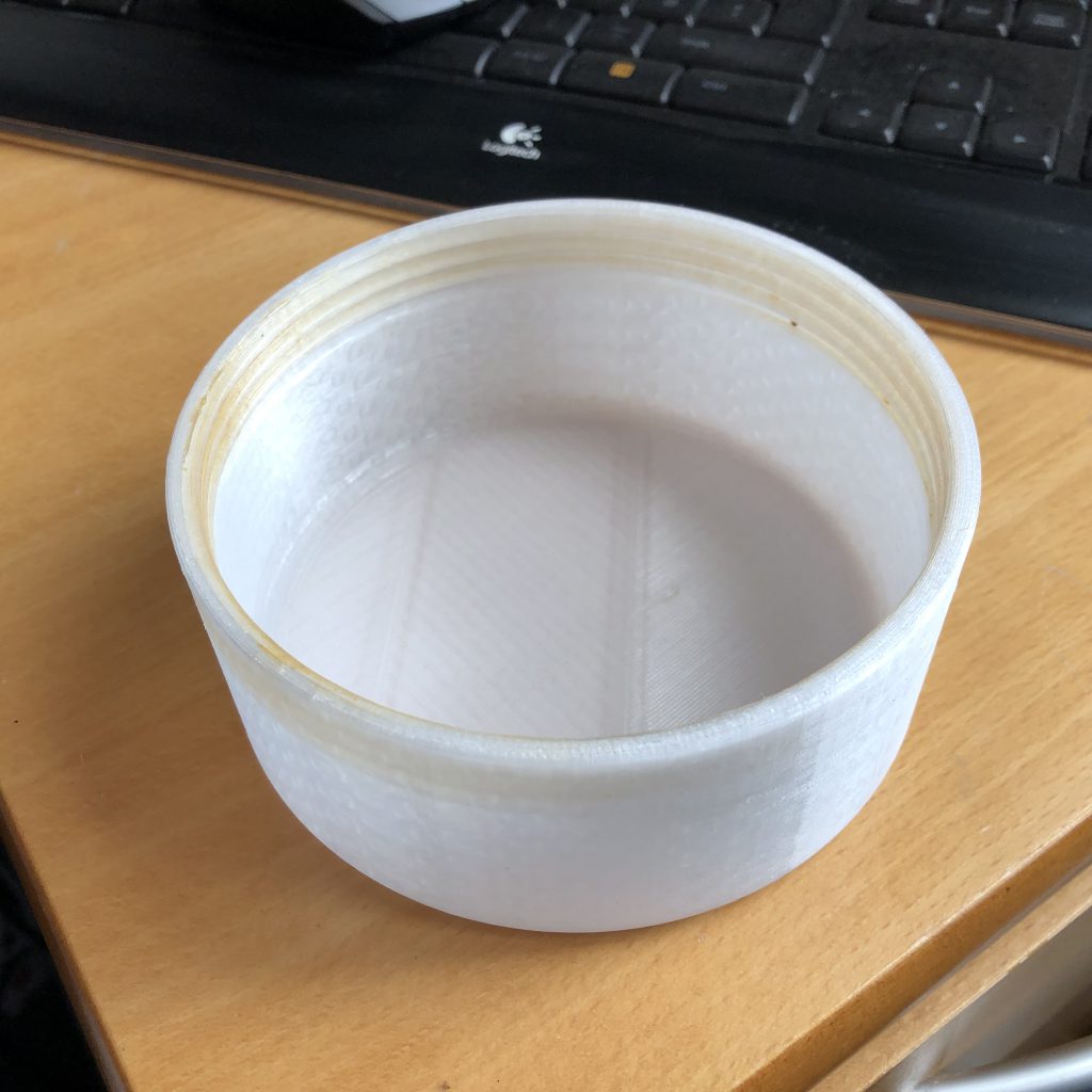
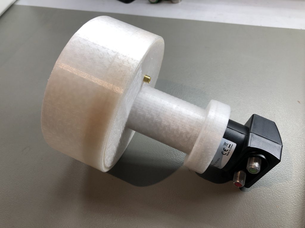
To protect the POTY feed, I made a holder in PTG that is UV resistant and on top a lid with thread to close it. the copper pipe is coming through the bottom with a 40mm holder and attachment for the LNB.
if you want the STL files – contact me or download:
POTY_STL
The top of the LNB is cut off and leaving about 15mm of the entrance out. Here on the end I made a holder. The holder is glued tight on the LNB, giving it good stability. The most right picture shows the unit gathered together.
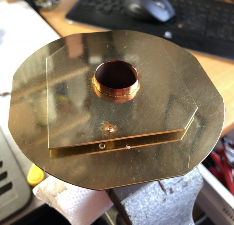
Receiving Bandpass filter for 739 Mhz
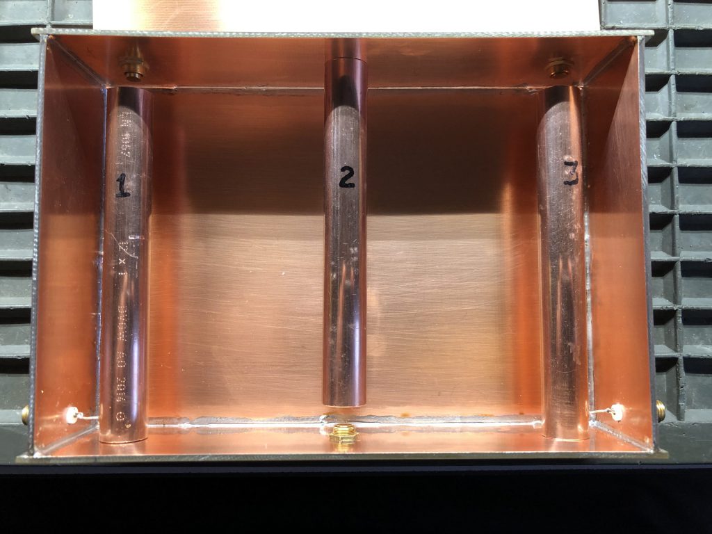
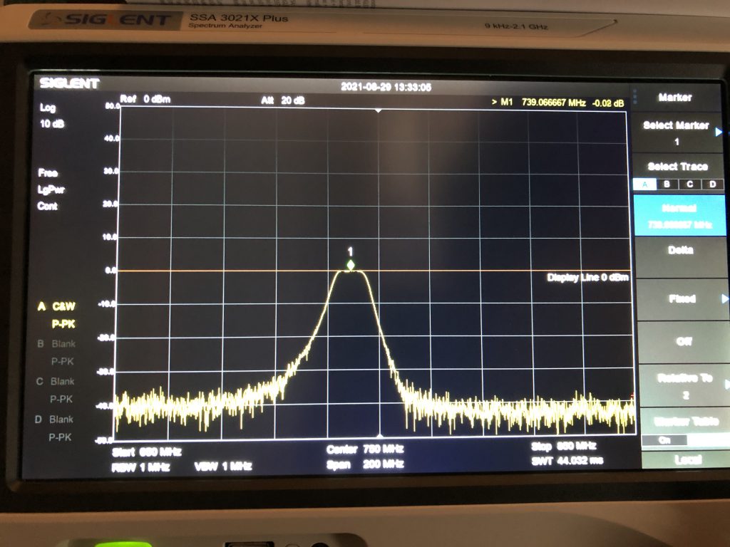
To get lower noise that can be a problem when living near a telephone distribution pole or other noisy equipment, I made a Interdigital Bandpass Filter for 739 Mhz. The filter is made of doublesided circuit board so that it can be sealed with solder. the 3 elements are 12mm copper pipe that was available in the local hardware store. construction details where calculated on the website of www.changpuak.ch and I must say that it calculates it very accurate.
Transmit filter 2,4 Ghz / preamplifier and Bias Tee
All 3 units are bought from Passion-radio.com and are as they came. Only thing I have changed, is on the Analog Devices CN-0417, that for my opinion was getting to hot. I found a piece of copper that is soldered on the SMA connector near the output. it still got very hot when 5V is attached, so I decided that the amplifier unit only gets 5V when PTT is active. That is made with a little relay unit, that I describe later. all 3 units are mounted on a aluminium plate in the box.
BiasTee unit is for sending 12V to the LNB on the same cable that the signal is comming on. I also have a 3 dB attenuator here in series with the BiasTee because the signal was to strong from the LNB to the Pluto receiver input. At first there was no attenuator but I could see that the Pluto was degrading the input signal when I received strong signals.
Assemling all in the box
I made a PTT circuit on a tiny veroboard so that the CN-0417 only gets 5V on transmit because it getting so hot, and also PTT for the PA. Its working very fine with a little delay about 1/4 to 1/2 sek – thats fine for SSB. I strugled a little with the F5OEO firmware to get the PTT working on GPO0 output on the Pluto, but after trying several times in upload of firmware from F5UII I stopped, because there is not coming any signal out on Pluto GP0 when keying PTT. I contacted DG9BFC Siegfried, that had written on the net about F5OEO and he told me that SDR Console only activates PTT when the drive is higher than zero – now it works fine. Circuit description / layout comes later.
Next I could’nt stand to try transmitting, to see how the poty is function and how the transmitter works with antenna. After testing that something is coming out and I can hear myself on the QO-100, I managed to get my tramsmit signal to be near my receive frequency. Suddenly there where a station on the frequency and my microphone was attached. It was DC3ZB Per, that lives near Frankfurt in Germany, that could give me a rapport on my signal. At first there was a minor problem with the sound of my voice and after about half and hour I was drifted about 1 Khz because of my not stabilized krystal osc. on Pluto board. But I found out that the PA works at 60% – about 5 Watt, and is not getting hot at all with 24V – thats fine. Yesterday I managed to move the satdish to its final destination, and getting the transceiver box mounted behind it. Look at the new pictures. To get rid of the frequenz drift when transmitting, I managed to install a Leo Bodnar mini GPSDO in the box. I also desided that the power of 12 V and 24 Volt, are located external. Antenna for the GPSDO is placed inside the box – there is no problem in receiving sat GPS signals inside the plastic box. 5V Power for the GPS unit, is delivered from a new PTT board I made because the first version was to high inside the box. The new PTT board will be made as a PCB that can be copied later.
My transceiver has now worked for about 2 month without problems, but after I finished building the remote power circuit and have mounted it in the garten house (look under other projects), there was a problem in connecting the ADALM Pluto – no respond. I though that I had made a failure in the connections, but all things where functioning well – so there must be a problem with the Pluto. I took the hole case inside to measure what was wrong, and found that it had changed the IP address back to default in the 192.168.x.x segment. Got it connected with Putty again and after many hours of changing the config.txt file and change startup settings with putty, I came to the following result:
After connecting Pluto to a PC with USB cable, It will be on a USB port that can be found under Ports in the device manager. Start Putty program and connect it to the Pluto on that port with serial connection type. A new window will come with credentials for login: root and password: analog – that will give a root login: #
The following commands must now be entered:
#fw_printenv // That will give a complete status of all settings
2 things are important when using external clock to the Pluto: refclk and source that can be found with:
#fw_printenv | grep ad936x_ext_refclk // Display setting for refclk
#fw_printenv | grep refclk_source // Display settings for source to clock
For me the clock frequenz must be 40 Mhz as the default clock on the board, but now external from GPSDO.
#fw_setenv ad936x_ext_refclk 40000000 // That will change the clock configuration to 40 Mhz (value in hz)
#fw_setenv refclk_source external // Change to external reference clock
I still had problems with the settings that after a power cycle was reset to defaults again, but here is the solution:
#fw_setenv qspiboot_extraenv true // This will preserve the settings still after a power off
To the last all settings have to be saved when entering new data with this command:
#pluto_reboot reset // That will apply changes and reboot the Pluto
SDR Console settings for frequenz definitions are – RX: 9749.982.000 TX: 8089.500.000
I hope that this will keep my setup in the Pluto for a while 🙂 – until now it works perfect.
Next thing is to dig a cabelduct from my garten house to the satdish.
Update: I have changed the Little Oscillator on the Pluto PCB for better frequenz stability to 0.5ppm. Because of that,
it is no longer need for the Leo Bodnar GPSDO, that I have taken out. The extra 2.4 Ghz filter is also taken out, because
the CN-417 preamplifier has a filter onboard. Input filter has also been taking out, because it will be used in my new setup
for my caravan. Automatic Dish on roof of caravan, will do auto search for QO-100 – but this will be told of in a new description
in the near future here :-).