I have several instruments on my workbench that need a stable reference frequenz to get a correct alignment and showing the same values. Today many takes the reference from GPS satellites, that have a very stable frequenz to get the correct position on the map. My circuit is made with a good 10 Mhz oscillator that is mounted in a owen, so that it is not drifting with the surrounding temperature. The 10 Mhz signal is then compared to the signal from a GPS receiver output trough a PLL circuit that corrects the 10 Mhz oscillators frequenz to be accurate.
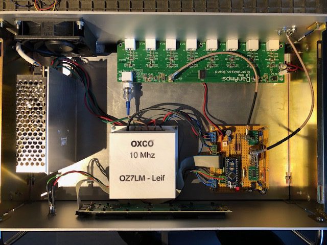
To distribute the 10 Mhz reference signal, I got a PCB from DanAmps on a marked sale, that has 8 outputs with independed signal to each other, and also gives a square output to my PLL circuit. Full description of each circuit is shown here after, but first a block diagram to show the context.